May 26th 2025
When designing photonic integrated circuits (PICs), it is tempting to focus purely on internal optical performance. However, a successful PIC design must also consider how the chip will be connected to the outside world. In this second part of PHIX’s blog series on a system-level approach to PIC design, we explain why mode field matching is crucial for achieving high-performance, cost-effective, and scalable photonic modules.
The value of early manufacturability considerations
Manufacturing optoelectronic modules based on PICs demands careful consideration of optical, electrical, mechanical, and thermal phenomena. While designers often optimize the optical functions inside the chip, overlooking external optical coupling can lead to poor performance, higher packaging costs, and delayed time-to-market.
As PHIX, we promote a system-level mindset that addresses manufacturability from the earliest design stages. Involving PHIX during the design phase allows your PIC to be optimized not just for optical performance, but also for reliable, efficient, and scalable assembly. To support this, we provide comprehensive PIC Design Guidelines documentation. This blog takes some bite-sized recommendations from that document on the topic of mode field matching, a key concept for low-loss optical interfaces.
Understanding mode field matching
In fiber-coupled photonic systems, light must transition between optical fibers and on-chip waveguides. Each of these components supports a specific optical mode, characterized by its mode field diameter (MFD), which is the effective width of the light beam.
Mode field matching ensures that the optical modes on both sides of the interface are as similar as possible in size and shape. If the MFDs are mismatched, a significant portion of the light will be lost at the interface. Such losses directly impact system performance, especially in the most demanding applications, where every photon counts.
Challenges and solutions in mode field matching
Mode field mismatches often exist between optical fibers and PIC waveguides. Most standard optical fibers, such as SMF-28, have a mode field diameter of about 10 µm, while typical on-chip waveguides, especially in platforms like silicon photonics, can have MFDs as small as 1–2 µm. Bridging this difference is non-trivial.
The following solutions can mitigate mode mismatch.
On-chip spot size converters
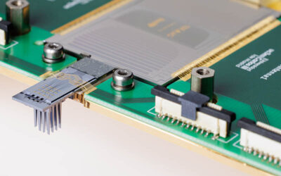
If your PIC foundry supports a spot size converter (SSC) structure for your chip material, then this is the recommended place to start. Even if you cannot expand the waveguide mode field to the full fiber MFD, having the largest possible mode field on the chip will help to obtain more relaxed alignment tolerances and therefore improved manufacturability.
Lowest loss
Integrated on the PIC itself
Not available on all PIC platforms
May allow only a partial mode field conversion
Suspended waveguide tapers for SiPh require special attention in packaging
PHIX spot size converters
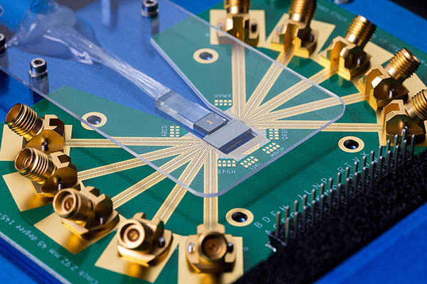
As an alternative or a complimentary solution to on-chip SSCs, PHIX offers off-chip SSCs that are attached to the fiber array. These are high-precision optical interposers made of ion-exchanged glass (IONext) or silicon nitride (SiN). PHIX SSCs cater to a variety of PIC waveguide mode fields (both circular and elliptical), optical fiber types, pitches, and channel counts. PHIX keeps a selection of these powerful photonics packaging building blocks available as standard off-the-shelf components.
Available for all PIC platforms
Scales well to volume (SiN variety)
Lithographically defined waveguides
Suitable for high channel counts
Takes up some additional space
Adds a component to the BOM
Adds an assembly step to the packaging
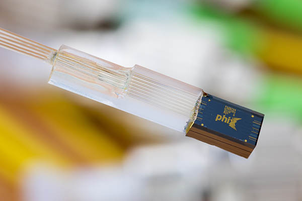
Fiber array with a silicon nitride PHIX spot size converter attached
Ultra-high numerical aperture fibers
Ultra-high numerical aperture (UHNA) fibers offer an alternative mode field matching solution. They are manufactured by splicing short pieces of UHNA fiber to regular fibers inside the v-grooves of a fiber array. This results in a reduced MFD at the interface without increasing the size of the package. On the other hand, the positioning of UHNA fibers inside a fiber array is not lithographically defined, so a lower and less repeatable coupling performance may result when compared to PHIX SSCs, especially for higher channel counts.
Requires no extra off-chip components
Takes up no extra space
Can outperform PHIX SSCs for low channel counts
Only a limited mode field reduction possible
Doesn’t scale well to high channel counts
Often does not support polarization maintaining requirements
Each solution involves trade-offs between optical loss, fabrication and assembly complexity, and cost. PHIX’s expertise lies in helping designers choose the best (combination of) techniques for their specific application, manufacturing volume, and cost targets. By involving PHIX early in the design process, our critical feedback on mode field matching and manufacturability will pay dividends in the final device. A design that prioritizes manufacturability alongside performance is far more likely to achieve cost-effective scalability and timely market adoption.
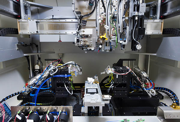
Manufacturing equipment at PHIX for automated fiber array attachment to PICs
Taking the next step
Mode field matching may seem like a technical footnote during the creative early stages of PIC design. In reality, it’s a foundational principle that enables the transition from innovative ideas to manufacturable optoelectronic devices. At PHIX, we’re ready to help you navigate this and other system-level considerations to bring your photonic innovations to life!
To learn more, explore this blog series and our PIC Design Guidelines and reach out to PHIX early in your development process. Together, we can build photonic devices that are not only groundbreaking, but also manufacturable, scalable, and successful.
Download our Design Guidelines (.pdf)
To help you optimize your PIC design for low-cost and low-risk packaging and select the most suitable standardized package type, we offer you our PHIX Design Guidelines document as a free download.